Images are representations only.
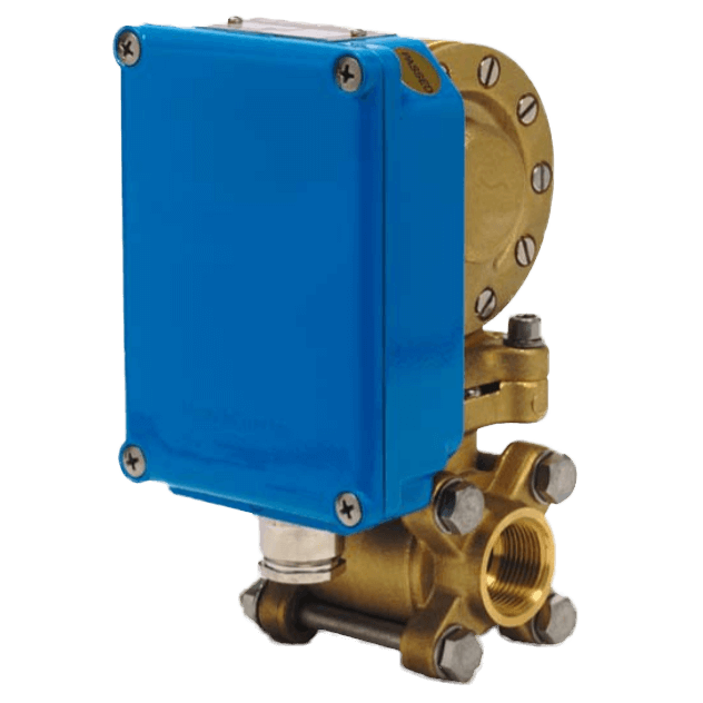
V-Series Flow Monitor
Brand: ElettaThe Eletta Flow Monitor’s function is based on the proven and dependable differential pressure principle. This is perhaps the oldest and most widely used principle for flow metering, mainly because of its simplicity and its relatively low cost. The Eletta V-series Flow Monitor is used to control flow of liquids and gases in pipes from 15 to 500 mm. Through the adjustable SPDT micro switch it is possible to set one low or high flow alarm to protect expensive equipment in various piping systems. The switching point is highly repeatable, within < 2%. The Flow Monitor is insensitive to surrounding magnetic fields and it combines the long-standing proven mechanical function with outstanding reliability. Together with an exceptionally sturdy and robust design, this makes it extremely well suited for difficult environments. The V-series comes in two measuring ratios designated V1 and V15, which means that the V1 has a flow measuring span of 1:2 and the V15 has a span of 1:5. Like all Eletta Flow Monitors the V-series can monitor both liquids and gases. Benefits:
Specifications
Brand
Approvals & Certifications
- CE
- EMC 89/336/EEC (EN 50081-1 & 50082-2)
- IEC Ex, 60079-0: 2007, 60079-11: 21007, 60079-26: 2006
- PED 97/23/EG
Approvals & Certifications
- ISO 9001, 14000
BSP Connection
- 1” BSP Female
- 1/2” BSP Female
- 1-1/2” BSP Female
- 1-1/4” BSP Female
- 3/4” BSP Female
Current
- Breaking Current: 15 A at 125 Vac
- Breaking Current: 15 A at 250 Vac
- Breaking Current: 15 A at 480 Vac
Electrical Rating
- Rated Voltage: 480 Vac / 15 A
Environmental Protection
- IP65
- IP66
- NEMA 4
Flange Size - 1-1/2” (DN 40)
- 1-1/2” (DN 40) - 150# ANSI
- 1-1/2” (DN 40) - PN 16
Flange Size - 1-1/4” (DN 32)
- 1-1/4” (DN 32) - 150# ANSI
- 1-1/4” (DN 32) - PN 16
Flange Size - 1” (DN 25)
- 1” (DN 25) - 150# ANSI
- 1” (DN 25) - PN 16
Flange Size - 1/2” (DN 15)
- 1/2” (DN 15) - 150# ANSI
- 1/2” (DN 15) - PN 16
Flange Size - 10” (DN 250)
- 10” (DN 250) - 150# ANSI
- 10” (DN 250) - PN 16
Flange Size - 11” (DN 275)
- 11” (DN 275) - 150# ANSI
- 11” (DN 275) - PN 16
Flange Size - 12” (DN 300)
- 12” (DN 300) - 150# ANSI
- 12” (DN 300) - PN 16
Flange Size - 14” (DN 350)
- 14” (DN 350) - 150# ANSI
- 14” (DN 350) - PN 16
Flange Size - 16” (DN 400)
- 16” (DN 400) - 150# ANSI
- 16” (DN 400) - PN 16
Flange Size - 18” (DN 450)
- 18” (DN 450) - 150# ANSI
- 18” (DN 450) - PN 16
Flange Size - 2-1/2” (DN 65)
- 2-1/2” (DN 65) - 150# ANSI
- 2-1/2” (DN 65) - PN 16
Flange Size - 2” (DN 50)
- 2” (DN 50) - 150# ANSI
- 2” (DN 50) - PN 16
Flange Size - 20” (DN 500)
- 20” (DN 500) - 150# ANSI
- 20” (DN 500) - PN 16
Flange Size - 3-1/2” (DN 90)
- 3-1/2” (DN 90) - 150# ANSI
- 3-1/2” (DN 90) - PN 16
Flange Size - 3” (DN 80)
- 3” (DN 80) - 150# ANSI
- 3” (DN 80) - PN 16
Flange Size - 3/4” (DN 20)
- 3/4” (DN 20) - 150# ANSI
- 3/4” (DN 20) - PN 16
Flange Size - 4-1/2” (DN 114)
- 4-1/2” (DN 114) - 150# ANSI
- 4-1/2” (DN 114) - PN 16
Flange Size - 4” (DN 100)
- 4” (DN 100) - PN 16
- 4” (DN 100) - 150# ANSI
Flange Size - 5-1/2” (DN 140)
- 5-1/2” (DN 140) - 150# ANSI
- 5-1/2” (DN 140) - PN 16
Flange Size - 5” (DN 125)
- 5” (DN 125) - 150# ANSI
- 5” (DN 125) - PN 16
Flange Size - 6-1/2” (DN 165)
- 6-1/2” (DN 165) - 150# ANSI
- 6-1/2” (DN 165) - PN 16
Flange Size - 6” (DN 150)
- 6” (DN 150) - 150# ANSI
- 6” (DN 150) - PN 16
Flange Size - 7-1/2” (DN 190)
- 7-1/2” (DN 190) - 150# ANSI
- 7-1/2” (DN 190) - PN 16
Flange Size - 7” (DN 175)
- 7” (DN 175) - 150# ANSI
- 7” (DN 175) - PN 16
Flange Size - 8” (DN 200)
- 8” (DN 200) - 150# ANSI
- 8” (DN 200) - PN 16
Flange Size - 9” (DN 225)
- 9” (DN 225) - 150# ANSI
- 9” (DN 225) - PN 16
Flow Rate
- 0.4 to 25,000 L/minute
Hysteresis
- Micro Switch: 10 %
Load
- Resistive Load: 125 Vdc at 0.4 A
- Resistive Load: 2 A at 30 Vdc
- Resistive Load: 230 Vdc at 0.2 A
Materials of Construction
- Rubber Part: EPDM
- Rubber Part: FPM
- Rubber Part: Nitrile (HNBR)
Maximum System Pressure
- psi: 232 (kPa: 1,600, bar: 16)
NPT Connection
- 1” NPT Female
- 1/2” NPT Female
- 1-1/2” NPT Female
- 1-1/4” NPT Female
- 3/4” NPT Female
Repeatability
- < 2 %
Switch Type
- 1 Micro Switch SPDT
Temperature Range
- Control Unit: Standard 90° C (194° F) - Max.
- Pipe Section Control Unit: 120° C (248° F) - Max.
- Pipe Section: 250° C (482° F) - Max.
Wetted Materials
- 316 Stainless Steel
- 904L Stainless Steel
- Copper Alloy
- Epoxy Painted Cast Iron